Internal Combustion Engine Laboratory
Internal Combustion Engine Laboratory
The internal combustion engine facilities are located in the basement floor of Thermal Engineering Laboratory at NTNU. The facility has been developed by Prof. Terese Løvås, member of of the Thermo fluids Research Group. See also the Combustion Kinetics Group.
Fully Instrumented Diesel Engine
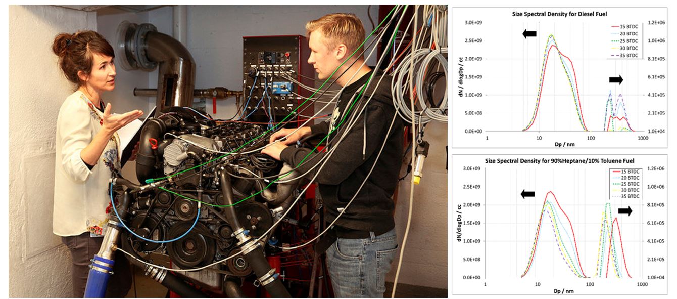 A six cylinder, 3.2 litre, Mercedes compression ignition engine is installed in the lab fitted to a Stuska water brake. The engine features a variable geometry turbo charger and a high pressure common rail injection system. The engine has been installed with a full suite of diagnostic instrumentation run though National Instruments hardware and LabView software. Engine management is managed by a user controlled ECU. In-cylinder combustion pressure along with engine speed, torque and various temperatures are recorded during experimentation. Exhaust gas emissions are recorded using a Horiba gas analyzer along with a Cambustion DMS500 to determine the size and number density of the exhaust particulate matter.
The engine is used with a range of fuels, including 1st generation and 2nd generation biofuels to gain greater understanding of the combustion of these fuels in the compression ignition environment. Of key importance and relevance is the impact of alternative fuelling on combustion particle matter emissions.
Optically Accessible Compression Ignition Combustion Chamber/Engine
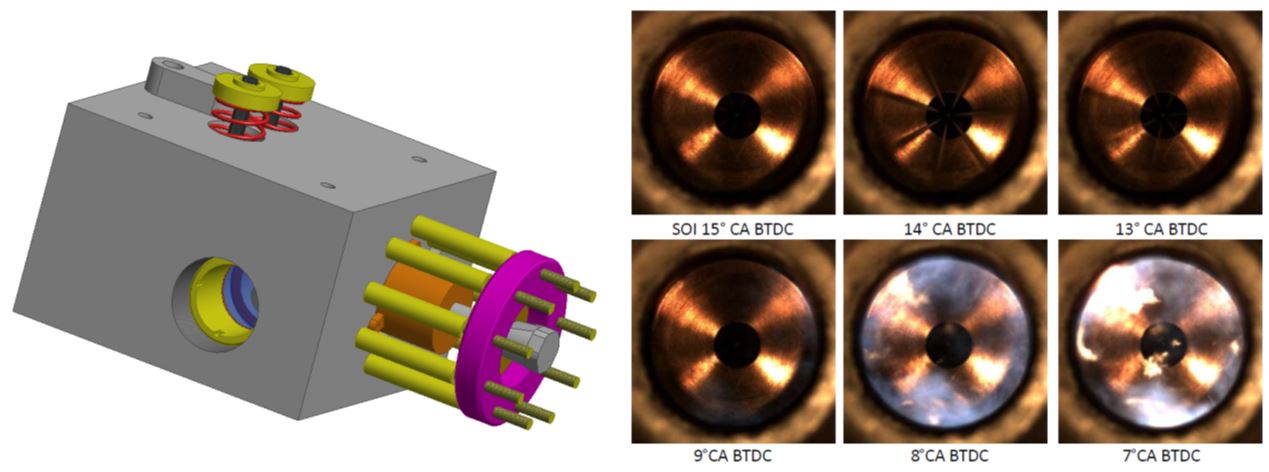
Currently under development and installation in the laboratory is an optically accessible combustion engine. The rig will operate as an engine but may also be described as a rapid compression machine. Installation consists of a large, 1.8 litre, single cylinder CI engine coupled to an AC dynamometer. The head of the engine has been replaced with a stainless steel section with an externalized combustion chamber fitted with sapphire windows. Injection is handle by a research common rail system. The system allows high speed imaging of the combustion to be conducted with an assessment of the auto-ignition and in-cylinder soot formation for a wide range of fuels.
High Pressure fuel injection test rig
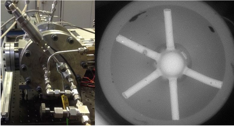
Currently being installed in the laboratory is an optically accessible pressure chamber, able to operate at a maximum of 40 bar, filled with an inert atmosphere of Nitrogen at ambient temperature. The chamber is fitted with identical injectors as used in the optical combustion chamber and the Mercedes engine and allows injection mass flow rate profile to be evaluated using the measured momentum flux of the fuel injection spray.
Optical access also allows high speed imaging of the sprays to be obtained to fully characterize the sprays for simulation purposes. The chamber is used in conjunction with a silicone molding technique and SEM photography to accurately determine the fuel injector’s internal geometry.
Contact
 Terese Løvås, Professor and Head of Department
Visiting address
Varmeteknisk lab (Thermal Engineering lab)
Kolbjørn Hejes v. 1A, NO-7491 Trondheim