Wet Gas Compressor and Multiphase Boost lab
Wet Gas Compressor and Multiphase Boosting Test Facility
The Wet Gas Compression and Multiphase Boosting lab are located in the basement of the Thermal Engineering Laboratory at NTNU. In combination the test rigs handle multiphase fluids ranging from pure liquid to pure gas. The facility has been developed by Prof. Lars E Bakken, Chief researcher Øyvind Hundseid and Sr. Engineer Erik Langørgen. See also the Processes and Power Research Group.
Wet Gas Compression

Objectives: Validate dry and wet gas compression system and to determine capabilities and constraints related to the impact of impeller-stage performance:
- Fluid behaviour and dynamics
- Corrosion and erosion tolerance
- Surge suppression and stall avoidance
- Transient operating conditions, including fluctuations in GVF
- Novel high-precision shaft torque control (static and dynamic)
- Electric motor and driver response and interactions
- Compression system control.
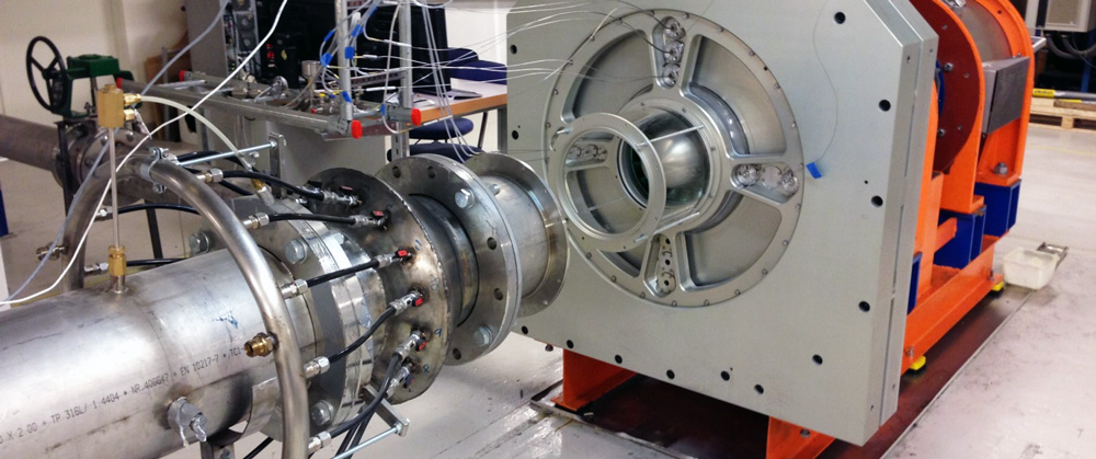
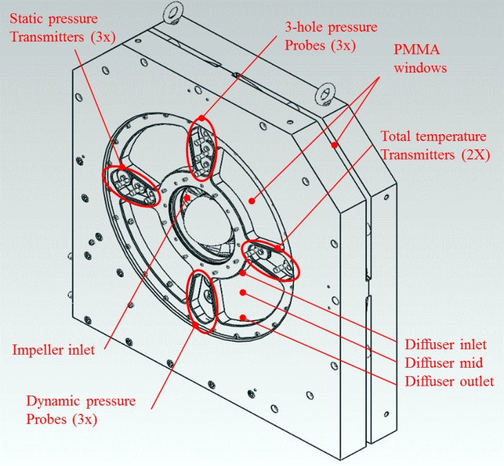
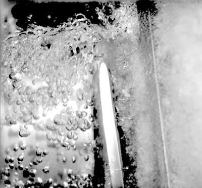
The wet gas impeller rig is an open-loop facility working at atmospheric air/water conditions. Visual observation of the wet gas flow regime is possible at the impeller in and outlet, diffuser and volute. Advanced flow visualization techniques at impeller and diffuser channels has been developed and validated. Comparison shows that the test rig results correspond well with high-pressure hydrocarbon performance.

Main dimensions and operating conditions
- Impeller outlet diameter (D2) 400 mm
- Diffuser with (b) 20 mm
- Diffuser ratio (D3/D2) 1.7
- Inlet hub diameter 250 mm
- Outlet pipe diameter 200 mm
- Suction conditions Atmospheric
- Test fluids; Air/water
- Air-flow range 0-3 kg/s
- Water-flow range 0-5 kg/s
- GVF range 99.93-100 %
- GMF range 40-100 %
- Drive 450 kW electric motor, 500 - 11000 RPM
Multiphase Boosting
Objective: Relate multiphase booster performance and instability to flow phenomena in the hydraulic channels, and analyse the ability to handle multiphase flow under steady state and transient operating conditions.

Main features
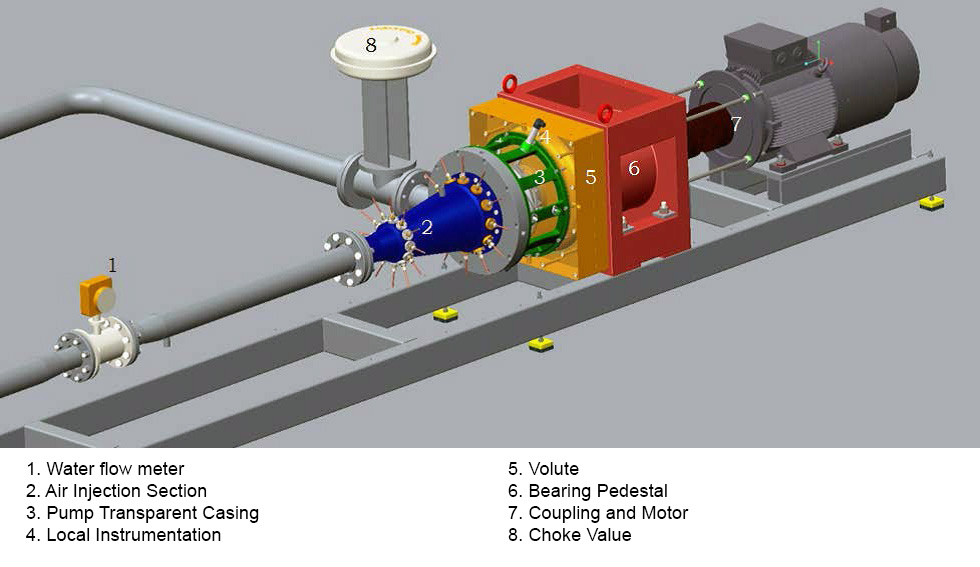
- Storage tank/separator, mainly consisting in external water supply and an horizontally placed tank, which acts as a simple separator
- Main pump loop
- Compressed air system, filtering and processing the gas flow before injection
- Inlet mixing section, where the desired upstream two-phase flow conditions are created
- Metering section, with global and local measurements of the main parameters involved in performance calculations
- Advanced flow visualization techniques at impeller and diffuser channels
Operating conditions
- Gas Volume Fraction 0 - 40 %
- Volume Flow Rate 0 – 200 m3/h
- Rotational Speed 0 – 2500 rpm
- Inlet Pressure 1 - 6 bar
- Drive 70 kW
Experimental setup of the Multibooster rig

Contact
Visiting address
Varmeteknisk lab (Thermal Engineering lab)
Kolbjørn Hejes v. 1A, NO-7491 Trondheim

 Professor Lars Eirik Bakken