MC-lab - IMT
-
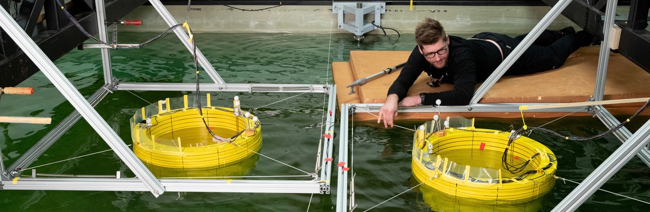 Marine cybernetics laboratory
 -

-
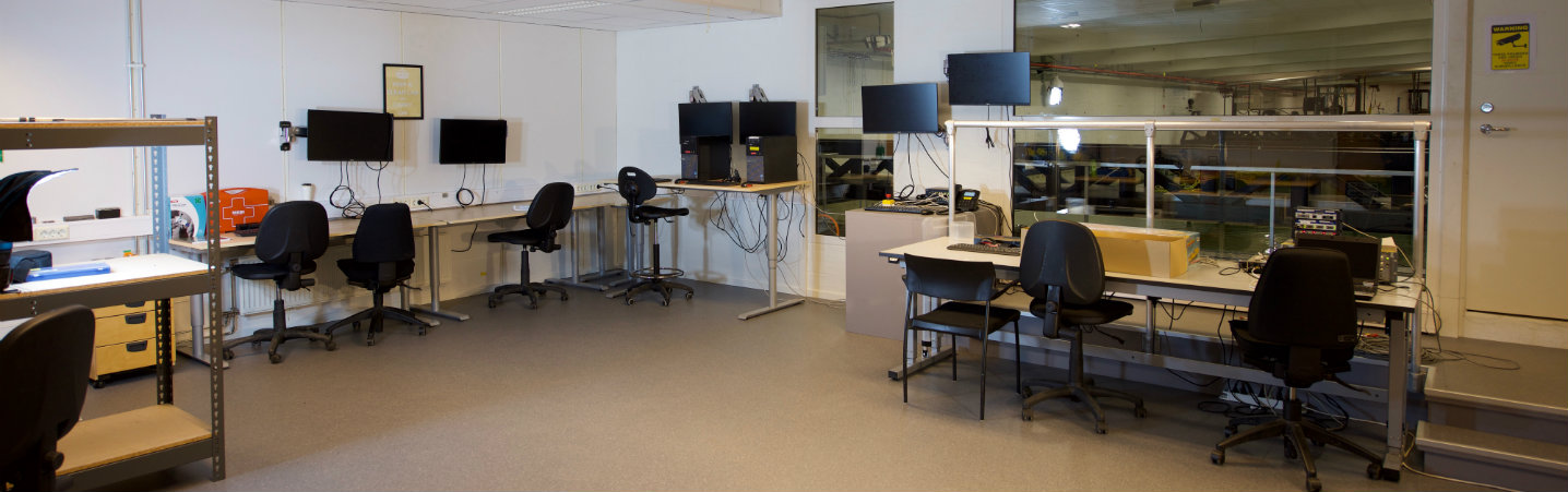 Marine cybernetics laboratory control room
 -
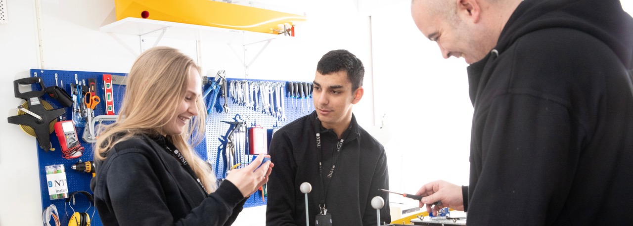

Marine cybernetics teaching laboratory


The marine cybernetics laboratory is a small wave basin, located in what was originally a storage tank for ship models made out of paraffin wax.
The facility is especially suited for tests of motion control systems for marine vessels, due to the relatively small size and advanced instrumentation package.
It is also suitable for more specialized hydrodynamic tests, mainly due to the towing carriage. The carriage is set up for both towing tests and test mounted in a spring system.
The MC-lab is operated by the Department of Marine Technology. It is mainly used by Master students and PhD candidates, but it can also be made available for external users.
The software in use was developed using rapid prototyping techniques and automatic code generation under Matlab/Simulink and Opal. The target PC onboard the vessel runs the QNX real-time operating system while experimental results are presented in real-time on a host PC using Labview.

Basin
- Length from wavemaker flap to beach: 32 meters (37.5 meters to end of tank)
- Depth maximum: 1.5 meters
- Width: 6.4 meters
Wave maker
The wave-maker in MC-LAB is a Bosch-Rexroth motor-controlled flap that is hinged in the bottom. The bottom hinge is approximately 75cm above the bottom floor and the flap is 6.4m wide with the actuator in the middle.
The actuator is controlled by a Labview program where you can either run it in manual or automatic. In manual mode you can set your desired wave height and frequency, which will either give you regular waves or irregular (JONSWAP) waves.
The automatic mode can do sets of waves from a generated file. The file is generated by the user and can be both regular and irregular waves.
The output waves will be measured with wave-probes, either conductive or ultrasonic. There’s a beach at the end of the tank which will dampen the waves and minimize reflections.
- Maximum speed: 0.59 m/s
- Maximum acceleration: 7.6 m/s^2
- Maximum amplitude: 0.25 m (flap motion)
- Maximum time period: 1.5 sec (You can run longer periods, but waves become gradually worse the longer they get)
MOCAP
In MC-LAB there are two separate mocap-systems. One is mounted on the carriage and the other is stationary on the walls around the tank.
The mocap that is mounted on the carriage is commonly used for hydrodynamic testing, while the stationary one is mainly used for marine cybernetics testing.
For tracking of models under water we usually mount long, lightweight rods with markers on them that sticks out of the water.
MOCAP system 1, carriage
There are four Oqus cameras from Qualisys mounted on the front of the carriage that covers an area of approximately 3x6 meters. The setup is configurable to adapt to a wide range of testing setups, but usually the cameras are focused on the center area where most models are mounted.
MOCAP system 2, stationary
There are seven Oqus cameras from Qualisys mounted around the tank that covers an area of approximately 15x6 meters. This setup is also configurable to match the requirements of a wide range of tests.

Accuracy
The Qualisys system operates with sub-millimeter accuracy within its calibrated area.
Real Time data stream
The software, Qualisys track manager, will stream the positioning data in real time onto the local network, where ROS2 and Catman can subscribe to this stream to get the position coordinates.
DAQ
Hardware: HBK-Quantum X and MGC+
Software: Catman AP(Easy)
Typical signals that the daq can acquire are analog. It can measure full bridge, half bridge, voltage, current and some digital protocols like can-bus, tcp-ip. The most common sampling frequency is 200Hz, but it has the capability to sample up to 19200Hz depending on the hardware chosen.
It can also create digital channels based on live calculations from physical channels. All daq channels can be displayed both as numbers and plots in real time. Data can be saved in several different formats, csv, bin etc.
Models used for marine cybernetics
- C/S Voyager: 1m length, 0.3m wide, azimuth thrusters rear (2), bow thruster front (1)
- C/S Enterprise: 1m length, 0.22m wide, Voith Schneider thrusters rear (2), bow thruster front (1)
- C/S Arctic Drillship: 2.45m length,0.425m wide, azimuth thrusters (6)
- C/S Saucer: 0.5m diameter, Azimuth thrusters (3)
All models have a raspberry pi 4/5 running ROS2 for control. For positioning a ROS node grabs position data from the Qualisys stream on the network. The models also have an IMU onboard. All models are powered by 12VDC batteries with a capacity over 9Ah per battery.
Towing carriage
The carriage can be operated in manual or computer-controlled mode. The manual operation is done from the console on the carriage. There is made a special Labview and Opal application to setup regular or irregular movement of the different axes.
- Carriage measurements: 6x4,5 meters
- Carriage measurements with trailer: 6x8,5meters
- Speed: 0.05 – 2 m/s
- Acceleration/deceleration: 0.01-0.5 m/s^2
- Automatic control: No
- Manual control: Yes
- Range of travel: 0-20 meters
- Test section mount: 6x3 meters (this is the area where we can mount the model, between the trailer and carriage)