Turbulent Combustion Laboratory - Department of Energy and Process Engineering
Turbulent Combustion Lab

Facilities
Atmospheric Pressure Single Sector rigs
Atmospheric Pressure Single Sector rigs

The laboratory has a number of atmospheric pressure single sector rigs available, which feature a single bluff body or swirl stabilised flame. This flame stabilisation mechanism is widely used in gas turbine engine combustion chambers, allowing a number of practically relevant issues to be investigated on these geometrically simple configurations.
Key Features:
- Typical operating power 5-30kW
- The setups are highly modular and the combustion chamber geometry can be easily reconfigured
- Removable swirlers and bluff bodies allow the flame geometry to be tailored
- Quartz glass enclosures and overhead mirror system permits optical access from multiple view points
- Multiple pressure ports for dynamic pressure measurements
- Loudspeaker array to acoustically excite the flames, controlled using automated excitation script
Sample publication
Atmospheric Pressure Annular (APA) combustor
Atmospheric Pressure Annular (APA) combustor

The Atmospheric Pressure Annular combustor features a number of individual flames which are confined within an annular chamber. This design replicates the essential features of annular combustor chambers, which are widely used in gas turbine engines. This setup is used to study various relevant dynamic phenomena on a simplified laboratory apparatus.
Key Features:
- Typical operating power 80-150kW
- Modular design allows the number of flames to be changed, with options for 12 or 18 flames
- Removable swirlers and bluff bodies allow the geometry of each flame to be tailored
- Quartz glass enclosure and overhead mirror system permits optical access from multiple view points
- Multiple pressure ports for dynamic pressure measurements
- Loudspeaker array can be mounted on the annular combustor to acoustically excite the flames, controlled using automated excitation script
Sample publications
Intermediate Pressure Annular (IPA) combustor
Intermediate Pressure Annular (IPA) combustor
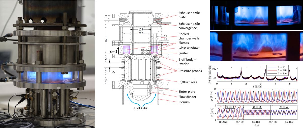
The Intermediate Pressure Annular combustor features a number of individual flames which are confined within an annular chamber. This design replicates the essential features of annular combustor chambers, which are widely used in gas turbine engines. This setup is used to study various relevant dynamic phenomena on a simplified laboratory apparatus. The design is different from the APA in that the combustor exit terminates with an annular choked nozzle, allowing the chamber to be pressurised. This boundary condition more accurately matches the conditions experienced in practical gas turbine engines.
Key Features:
- Typical operating power 200-400kW
- Modular design allows the number of flames to be changed, with options for 12 or 18 flames
- Removable swirlers and bluff bodies allow the geometry of each flame to be tailored
- Quartz glass enclosure permits optical access
- Multiple pressure ports for dynamic pressure measurements
- Water cooled combustion chamber
Measurement equipment
Measurement equipment

Researchers have access to a number of advanced diagnostics, including: high- and low-speed Particle Image Velocimetry (PIV) systems; a multi-component Laser Doppler Anemometry (LDA) system; multi-channel Hot Wire Anemometry (HWA) systems; a high-speed Planar Laser Induced Fluorescence (PLIF) system; and a number of high-speed cameras and high-speed image intensifiers. The lab is also well equipped with dynamic pressure sensors, photomultiplier tubes, and a large supply of optics and opto-mechanical equipment.
Laboratory Facilities
Laboratory Facilities
![]()
Each workstation can be reconfigured with different experimental setups. Each experimental workstation:
- An electrical power supply
- Pressurised air supplied from a dedicated compressor system (20,000 SLPM at pressures up to 7.5 Bar)
- A high temperature exhaust system
- Gas lines for a range of fuels, diluents and oxidisers, supplied from an isolated gas storage room. System commissioned for delivery of methane, ethylene, hydrogen, and ammonia.
- Large range of Mass Flow Controller devices for accurately metering fuel and air delivery. Operated remotely through digital control scripts.
- Access to multiple cooling water lines.
Find us
- Follow NTNU Thermo-Fluids
- Follow us on LinkedIn
- Follow us on YouTube