MC-lab - IMT
-
 Marine cybernetics laboratory
 -

-
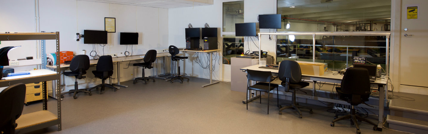 Marine cybernetics laboratory control room
 -

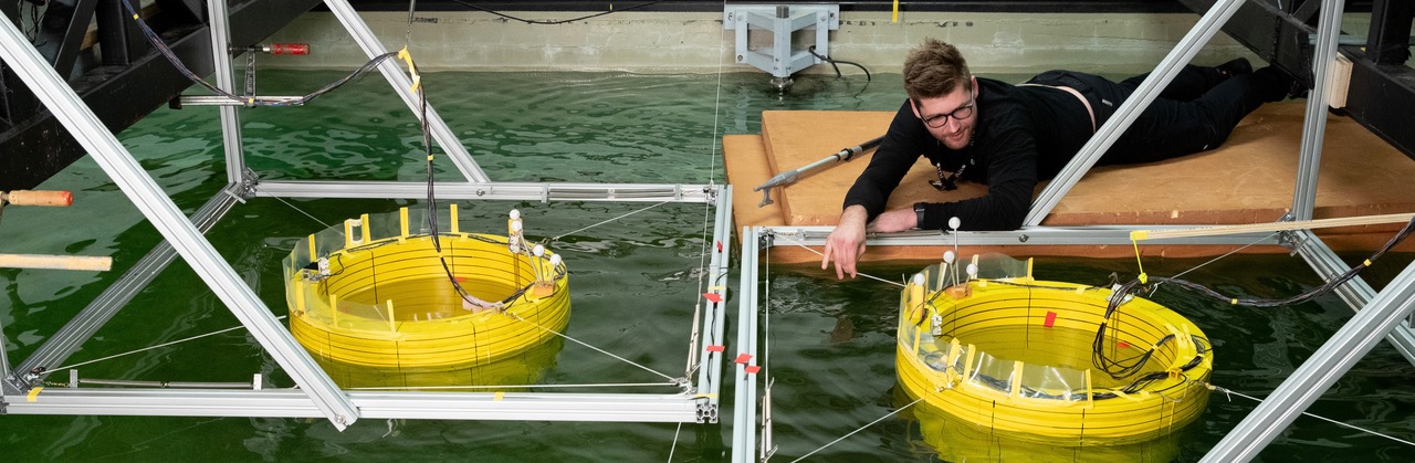
Marine cybernetics teaching laboratory


The marine cybernetics laboratory is a small wave basin, located in what was originally a storage tank for ship models made of paraffin wax.
The facility is especially suited for tests of motion control systems for marine vessels, due to the relatively small size and advanced instrumentation package. It is also suitable for more specialized hydrodynamic tests, mainly due to the advanced towing carriage, which has capability for precise movement of models in six degrees of freedom.
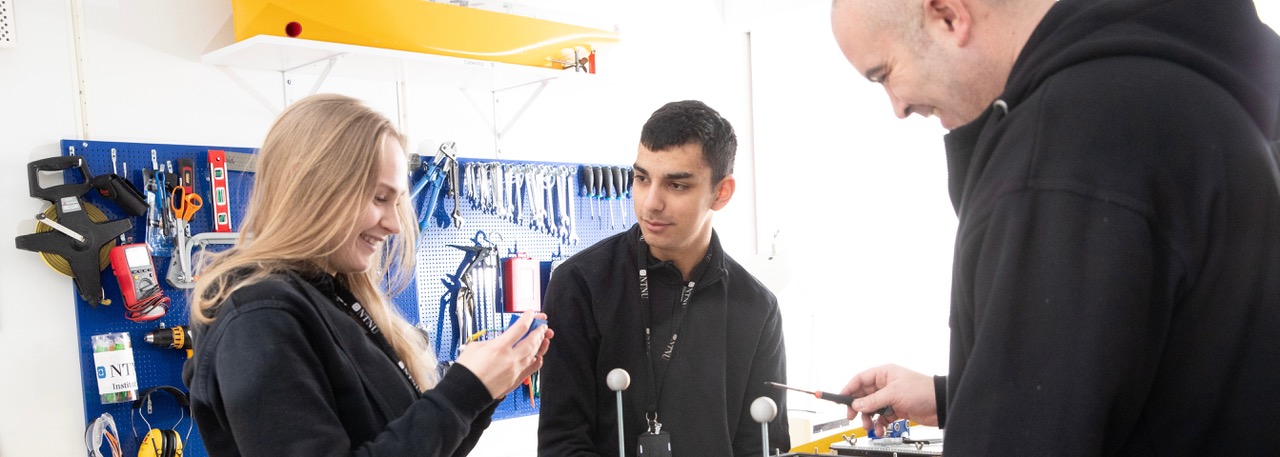
The MC-lab is operated by the Department of Marine Technology. It is mainly used by Master students and PhD candidates, but it is also available for external users.
The software in use was developed using rapid prototyping techniques and automatic code generation under Matlab/Simulink and Opal. The target PC onboard the vessel runs the QNX real-time operating system while experimental results are presented in real-time on a host PC using Labview.
Capacities:
|
Experimental set-ups:
|
Real-time positioning system
Qualisys supplies a range of hardware and software products for motion capture and analysis of movement data. The key components of the system are the Oqus cameras and the Qualisys Track Manager (QTM) software. For advanced analysis of the movement data Qualisys supplies third party software products such as Visual3D from C-Motion, Inc.
Measurement data can be exported in different standard formats for use in customer-developed and other third party software. The Qualisys products are designed to meet the highest demands for quality, simplicity, speed and precision. Systems, built from the Qualisys products, are flexible, mobile and expandable and are therefore easy to adapt to varying needs in industry, research and clinical use.
Tracking a model vessel's motions under different wave, current or wind conditions is one of the fundamental tasks at a hydrodynamics lab or a naval test site. Traditionally, this has been accomplished with potentiometer systems attached to a model or with bulky and expensive gyroscopes and accelerometers. Qualisys AB offers a easy, quick and functional way to obtain accurate 3D and 6 DOFs. With optical capture technology, your models remain completely unburdened by heavy sensors. Thanks to the low-mass optical targets, even very small and light models can be used.
Towing tank - In a towing tank, as few as 2 or 4 cameras can suffice, depending on the configuration. The cameras can be put on the towing carriage, which puts the model and the markers in the line of sight.
Oqus specifications:
|
Camera output modes |
Marker coordinates, high speed video*, streaming video* |
|
Built-in camera display |
128 x 64 graphical high contrast OLED |
|
Camera body |
Custom, die-cast aluminum |
|
Camera size Oqus 100 |
185 × 110 × 124 mm (7.3 × 4.3 × 4.9 inches) |
|
Camera size Oqus 300/500 |
200 × 145 × 155 mm (7.9 × 5.7 × 6.1 inches) |
|
Weight including optics |
1.9 kg Oqus 100 – 2.1 kg Oqus 300/500 (4.2 – 4.6 lbs) |
|
Cooling |
Convection cooling |
|
Camera protection level* |
Water resistant IP67 housing available |
|
Operating temperature |
0-35 °C |
|
Firmware |
Upgradeable from host computer |
|
Position data noise level |
+/- 1 camera units |
|
Adjustable threshold |
Yes |
|
Frame buffer speed |
12.9 Gbyte/second |
|
Maximum frame buffer size |
1152 Mbyte |
|
Cabling |
Hybrid cable with Ethernet and power |
|
Wired communication |
Hubless daisy-chained Ethernet 802.3@100Mbps |
|
Wireless communication* |
WLAN 802.11b/g@54Mbps |
|
Power supply |
Daisy-chained power from mains adaptor |
|
Power |
36-72 VDC, 10-16 VDC (battery) at 30 W maximum |
|
Battery* |
Available Q4-2008 |
|
Lens types* |
Standard 40 degrees HFOV (many other options available) |
|
Strobe types supported* |
Infrared, red and blue/green |
|
3-SERIES |
|
|
CMOS sensor size (pixels) |
1280×1024 |
|
Maximum frame rate at full resolution and field-of-view |
500 fps |
|
Maximum frame rate at full resolution and reduced field-of-view |
10000 fps |
|
x-coordinate full scale range (camera units) |
82000 |
|
y-coordinate full scale range (camera units) |
65000 |
|
Maximum video frame rate (full resolution) |
500 fps |
|
Maximum video buffer capacity (full resolution) |
900 frames |
|
Maximum video buffer capacity (full resolution and frame rate) |
1.8 s |
* Optional accessory/feature - Qualisys reserves the right to change specifications without notice
Three of these cameras together with a PC are installed in McLab pr. 2010.
Wave maker with AWACS - delivered by DHI
The wave maker is a 6 meter width single paddle and is operated with a electrical servo actuator. The system is equipped with a Active Wave Absorption Control System (AWACS 2). The system has a DHI Wave Synthesizer which can produce regular and irregular waves.
Capacity of the wave maker:
- Regular waves H < 0.25, T = 0.3 – 3 s.
- Irregular waves Hs < 0.15 m, T = 0.6 – 1.5 s.
- Available Spectrums: JONSWAP, Pierson-Moskowitz, Bretschneider, ISSC, ITTC, …
- Wave controller update rate = 10 Hz
- No. wave gauge on paddle = 4
- Stroke length on actuator = 590 mm.
- Speed limit = 1.2 m/s.
Towing carriage
The carriage can be operated in manual or computer controlled mode. The manual operation is done from the console on the carriage. There is made a special Labview and Opal application to setup regular or irregular movement of the different axes.
Axes
The axis limits given in the table refers to the absolute coordinates in the remote control system. The ranges are the safe and practical limits, as of May 2005. These may be subject to change. Normal Speed is the speed used when returning to reference position.
|
Axis |
Min |
Max [m] |
Pos Error |
Normal Speed |
Max Speed |
Max Acc |
|
|
X |
Main Carriage (Gantry) |
-15.5 |
8.5 |
±20 |
0.5 |
2.0 |
0.5 |
|
Y |
Transverse carriage |
-2.4 |
2.4 |
±5 |
0.2 |
1.0 |
1 |
|
U |
small Carriage in X direction |
-0.4? |
0.4? |
±1 |
0.2 |
1.0 |
1 |
|
C |
Rotation Table |
|
|
±.1° |
|
|
|
|
Z |
Vertical Axis |
-0.2? |
0.2? |
±0.5 |
0.1 |
0.5 |
2 |
|
W |
Vertical Axis |
-0.2? |
0.2? |
±0.5 |
0.1 |
0.5 |
2 |
Positive direction is based on a manoeuvring type coordinates with Z and W positive downwards.

