Fluid Mechanics Laboratory and Wind Tunnel - Department of Energy and Process Engineering (EPT)
Fluid Mechanics Laboratory and Wind Tunnel

The NTNU Fluid Mechanics Laboratory is housed within Strømningsteknisk on the Gløshaugen campus. It includes several facilities designed for the investigation of fundamental fluid mechanics problems.
Access and external inquiries
Projects supervised by experimental professors within the Thermo-Fluids group have priority access to the facilities. However, our facilities are available to external users for testing, and will have costs associated with them. If there is capacity to take on such a project, support will be provided throughout its course: from understanding the specific needs, designing appropriate experiments, and executing the project. Get in touch with us with your inquiries through this contact form:
Fill out contact form for inquiries on testing and experimentation
Facilities
Large-Scale Wind Tunnel
Large-Scale Wind Tunnel

The Large-Scale Wind Tunnel at NTNU is the largest wind tunnel of its kind in Norway. It is primarily used for research. Some past studies have focused on measurements of the flow around model wind turbines, aerodynamics of airfoils, bridge aerodynamics and fundamental turbulence measurements. The wind tunnel is also used for teaching, particularly in the courses TEP4175 Wind Turbine Design, TEP4160 Aerodynamics and TEP4112 Turbulent Flows.
- Test-section dimensions: 2.7 m x 1.8 m x 11.1 m (width x height x length)
- Maximum velocity: 22 m/s (80 km/h)
- Special features:
- Optical access for advanced image-based flow diagnostics
- A 6-component balance to measure forces encountered by various models.
- A forced vibration rig which also houses a second balance is used to study bridge desks.
- An active turbulence grid which can recreate real-life conditions and produce atmospheric conditions such as wind gusts.
- A 3-axis traverse.
- Sample publications: Aliferis et al. (2019), Li & Hearst (2021), Jooss et al. (2022) and Kildal et al. (2023)
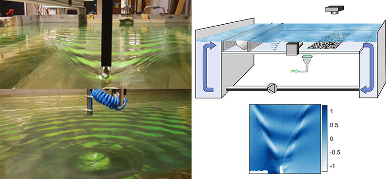
Water Channel
Water Channel

Water has slower dynamics compared to air, making it easier to study fundamental fluids problems. The recirculating open-surface water channel makes it possible to do just this. Past studies include investigating the development and decay of turbulence, wall-bounded flows, flow around immersed bodies, wind turbine wakes (by matching non-dimensional quantities) and features of ocean surface waves. This facility also contains a wind tunnel on top of the water surface. This allows us to recreate conditions at the ocean surface (both on the water side and the atmosphere) and facilitates the study of wind-wave interactions and CO2 absorption by the oceans. It houses a wave maker to produce tailored ocean waves and a towing rig. It also includes an active turbulence grid which allows us to tailor the turbulence conditions in both, the water and air sides, separately. This is a one-of-a-kind facility in the world.
- Test-section dimensions: 1.8 m x 0.8 m x 11.2 m (width x height x length)
- Maximum velocity: 1 m/s (2 knots) in water side and 10 m/s in wind side
- Special features:
- Full optical access enabling the use of advanced image-based flow diagnostics.
- Wave maker to generate tailored ocean surface waves.
- 3 axis traverse and towing rig (1 m/s)
- An active turbulence grid that can set (turbulent) flow conditions in both the water and air sides separately.
- Sample publications: Jooss et al. (2021), Smeltzer et al. (2023) and Hillestad et al. (2024)
- Sample project: GLITR, WaTurSheD
Small-Scale Channel Flow Facility
Small-Scale Channel Flow Facility
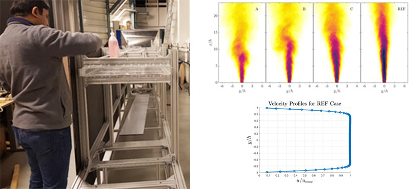
The small-scale channel flow facility was designed to investigate canonical channel flows. The facility has full optical access and includes an active grid at the inlet where each wing is independently controllable. There is also a movable injection plate where different gases can be mixed into the flow or suction or blowing can be applied. The closed channel test-section can also be removed, thus creating a planar jet facility with an active grid. A water channel of dimensions 0.6 m x 0.1 m x 1.3 m (width x height x length) with quartz window can also be added at the jet exit, producing an air-water channel to investigate oxygen dissolution dynamics in wind-driven channel flows. This facility was partially funded by the NFR Project DiHi-Tech.
- Test-section dimensions: 0.6 m x 0.05 m x 6 m (width x height x length)
- Maximum velocity: 20 m/s
- Special features: Active grid with each wing controlled independently. Porous wall for gas or air injection. Complete optical access. Can also be configured as a planar jet or an air-water channel.
- Sample publications: Kamruzzaman et al. (2021), Asadi et al. (2022), Asadi et al. (2022)
Von Kármán Mixing Tank
Von Kármán Mixing Tank
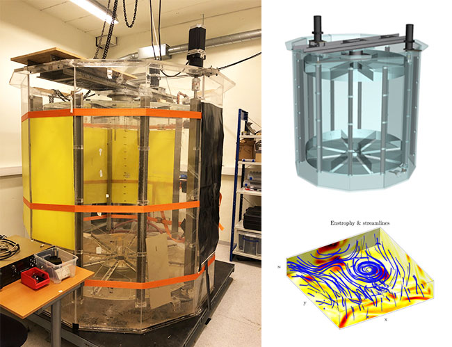
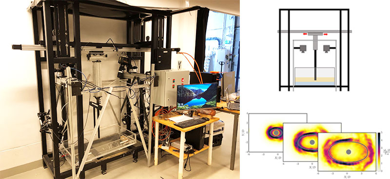
The von Karman tank produces stationary, homogeneous turbulence conditions with relatively large Reλ (up to 1000) in its central region. Such conditions are relatively close to homogeneous isotropic turbulence, as considered in many DNS studies, and therefore are suitable for fundamental turbulence research. The impellers can be operated in several modes (e.g. steady rotation, modulated rotation, random rotation), which provides control over the forcing mechanism. This facility was originally located at the University of Cambridge but has been relocated along with its original researchers (Prof. Worth and Prof. Dawson) to NTNU.
- Test-section dimensions: 2 m diameter (hexagonal), 1.25 m impellers distance, 5 tons of water.
- Maximum impeller speed: 3.5 rpm
- Special features: Supports modulated/random rotation of impellers. Complete optical access.
- Sample publications: Worth et al. (2010), Lawson & Dawson (2014), Lawson & Dawson (2015), Aligolzadeh et al. (2023)
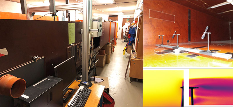
Wave-Current Flume
Wave-Current Flume
The wave-current flume has been used for studying water waves propagating atop vertically-sheared currents. Previous experiments have measured ship waves and ring waves in the presence of shear currents, confirming theoretical predictions. In addition, measurements of the directional wave spectrum have been used for developing and testing remote sensing methods of vertically-sheared currents.
- Test-section dimensions: 2 m x 2 m x 0.15 m (length x width x height)
- Maximum velocity: 1 m/s
- Special features: Flow-conditioning systems to produce vertically-sheared currents of different forms. Experimental techniques for measuring the topography of the water surface in space and time.
- Sample publications: Smeltzer et al. (2019a), Smeltzer et al. (2019b)
Aerodynamic Wind Tunnel
Aerodynamic Wind Tunnel
The aerodynamic wind tunnel at NTNU is a small tunnel intended for aerodynamic style measurements. It contains multiple force balances and has been used for various aerodynamic studies in the past, including sports garments aerodynamics, sports helmet aerodynamics, and small-scale wind turbine aerodynamics.
- Test-section dimensions: 1 m x 0.5m x 5 m (width x height x length)
- Maximum velocity: 35 m/s
- Special features: 6 component force balance
- Sample publications: Skeide et al. (2020), Helvig et al. (2021)
Gunt Aerodynamics Tunnel
Gunt Aerodynamics Tunnel

The small GUNT aerodynamics tunnel is primarily used for teaching. It has a series of built-in infrastructure making it ideal for student demos and exercises. This is a commercial product made by GUNT GmbH and more details can be found here. It is used in the teaching activities of FENT2002, FENA2002, FENG2002 Fluid Mechanics & Hydraulics.
- Test-section dimensions: 0.29 m x 0.29 m x 0.42 m (width x height x length)
- Maximum velocity: 28 m/s
- Special features: Integrated force balance, pressure measurements, and smoke wand
Non-Newtonian Towing Rig
Non-Newtonian Towing Rig
The non-Newtonian towing tank has been used to measure the propagation of jamming fronts in dense cornstarch suspensions. Jamming fronts generated around a towed cylinder have been studied, but the setup is also intended for use with other towed bodies and fluids.
- Test Section Dimensions: 0.5 m x 0.5 m x 1.1 m (width x height x length)
- Towing speed: 4 m/s (max)
- Sample publications: Rømcke et al. (2020)
Measurement Equipment
Measurement Equipment

The Fluid Mechanics Laboratory at NTNU is extremely well equipped. In addition to the active grids and force balances directly integrated into the various facilities, the lab has moveable measurement equipment including:
Particle Image/Tracking Velocimetry (PIV/PTV) systems:
- Tomographic PIV / 4D-PTV: | 10 kHz – 1 MP | 1 kHz – 4 MP | 15 Hz – 25 MP |
- Stereoscopic PIV: | 20 kHz – 1 MP | 5 kHz – 4 MP | 15 Hz – 5.5 MP, 16 MP and 25 MP |
- Planar PIV / 2D-PTV with all the above configurations
Laser-Induced Fluorescence (LIF) systems:
- The above systems can also be used for LIF, which we primarily do in water using Rhodamine 6G.
Digital Image Correlation (DIC) systems:
- The above camera systems can also be employed for DIC when a non-contact method is needed to measure a model’s deformation or displacement.
Hot-wire anemometry (HWA) systems:
- Dantec StreamLine Pro constant temperature anemometry (CTA) systems – 8 channels
- Numerous single-wire and X-wire probes for use in air.
- Numerous single-wire and X-wire probes for use in water.
Laser-Doppler Anemometry (LDA) systems:
- 2-component LDA system.
Find us
Strømningsteknisk lab (see Mazemap)
Kolbjørn Hejes vei 2, NTNU
NO-7034 Trondheim
Norway
- Follow NTNU Thermo-Fluids
- Follow us on LinkedIn
- Follow us on YouTube
Designing wind turbines
A film from the course Energy from Environmental Flows.